Timing Pulleys
 Timing pulley 16T2,5 for timing belt width 6 mmNumber of articles in this product: 16
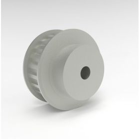 Timing pulley 20T2,5 for timing belt width 10 mmNumber of articles in this product: 16
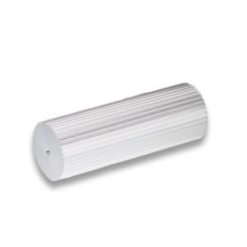


 Timing pulley 31T10 for timing belt width 16 mmNumber of articles in this product: 15
 Timing pulley 40T10 for timing belt width 25 mmNumber of articles in this product: 15
 Timing pulley 50T10 for timing belt width 32 mmNumber of articles in this product: 12
 Timing pulley 66T10 for timing belt width 50 mmNumber of articles in this product: 12

 Timing pulley 21AT3 for timing belt width 10 mmNumber of articles in this product: 17
 Timing pulley 28AT3 for timing belt width 16 mmNumber of articles in this product: 16
 Timing pulley 28AT5 for timing belt width 16 mmNumber of articles in this product: 13
 Timing pulley 38AT5 for timing belt width 25 mmNumber of articles in this product: 13
 Timing pulley 46AT5 for timing belt width 32 mmNumber of articles in this product: 13
 Timing pulley 42AT10 for timing belt width 25 mmNumber of articles in this product: 13
 Timing pulley 50AT10 for timing belt width 32 mmNumber of articles in this product: 12
Manufacturing and geometry of the perfect timing belt pulleys for your application
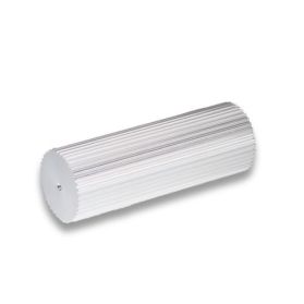
A belt drive consists of a belt and at least two pulleys. The positive drive pulley (also called synchronous pulley) has a concentric centre hole and a toothed circumferential surface. The tooth geometries of the timing belt and -pulley (profile & pitch) must be exactly matched to ensure a clean form fit of the two contact partners. Depending on the application and task, toothed pulleys can be equipped with additional guide elements, the flanges, to guide the toothed belt. In addition to the conventional machining processes of milling, turning, etc., primary moulding processes such as casting and powder-metallurgical pressing and sintering are also often used for larger quantities, series or large-series production. For the production all metallic and non-metallic semifinished materials are suitable, as long as they have sufficient strength and can be easily machined. The common materials used by Angst+Pfister are aluminium alloys, steel and cast iron as well as the plastics PA, PE and POM.
If we do not have the desired timing pulley in stock, or it is a special design, we can manufacture and rework it according to your specific requirements.
For the manufacturing process and correct functionality of the timing pulley the pitch circle, tip circle and root circle diameters are relevant
The pitch circle diameter dW describes the arc line in synchronous drives that forms the position of the tension cords in the timing belt when it is wrapped around the pulley. The pitch circle diameter is therefore placed outside the pulley contour and is usually marked with a semicolon line.
The tip circle diameter dK is the diameter of the circumferential surface of the timing belt pulley on which the timing belt is supported. This diameter can be measured directly with a suitable measuring device.
The root circle diameter dF forms the arc line connecting the bottom of the tooth gap.
Toothed pulleys – the following should be considered
Toothed pulleys used in drives with belt speeds of more than 30m/s must be balanced.
The toothed width of a toothed pulley with flanges should be selected slightly larger than the belt width. As a guide for the additional width, 1/4 to 1/5 of the pitch can be selected. For a 20 mm wide timing belt with profile AT10, for example, a toothed width of approx. 22m is selected.